You've got a brushless motor acting up. Maybe it's a drone that won't lift off. Or a RC car that just stutters. A breeze multimeter can catch roughly 80% of winding faults. You don't need a degree in electrical engineering to do it.
I've seen too a lot of most of us toss perfectly good motors when the real problem was a rough ESC or a loose sensor wire. So, testing a brushless motor with a multimeter isn't just about saving money. It's about fixing the right thing the first time.
Key Point
- Ensure all three phase pairs (U-V, V-W, U-W) show nearly equal resistance, typically 0.2–10 ohms. A mismatch of more than 10% signals a burnt winding.
- There should be no continuity between any phase wire and the motor casing. A beep indicates a short to ground, which makes the motor unsafe.
- Spin the shaft with a drill while measuring AC voltage across two phase wires. A healthy motor will produce a small voltage, often 0.5–2V, confirming back EMF generation.
- If your motor has Hall sensors, apply 5V and turn the shaft by hand. The sensor output should toggle between 0V and 5V.
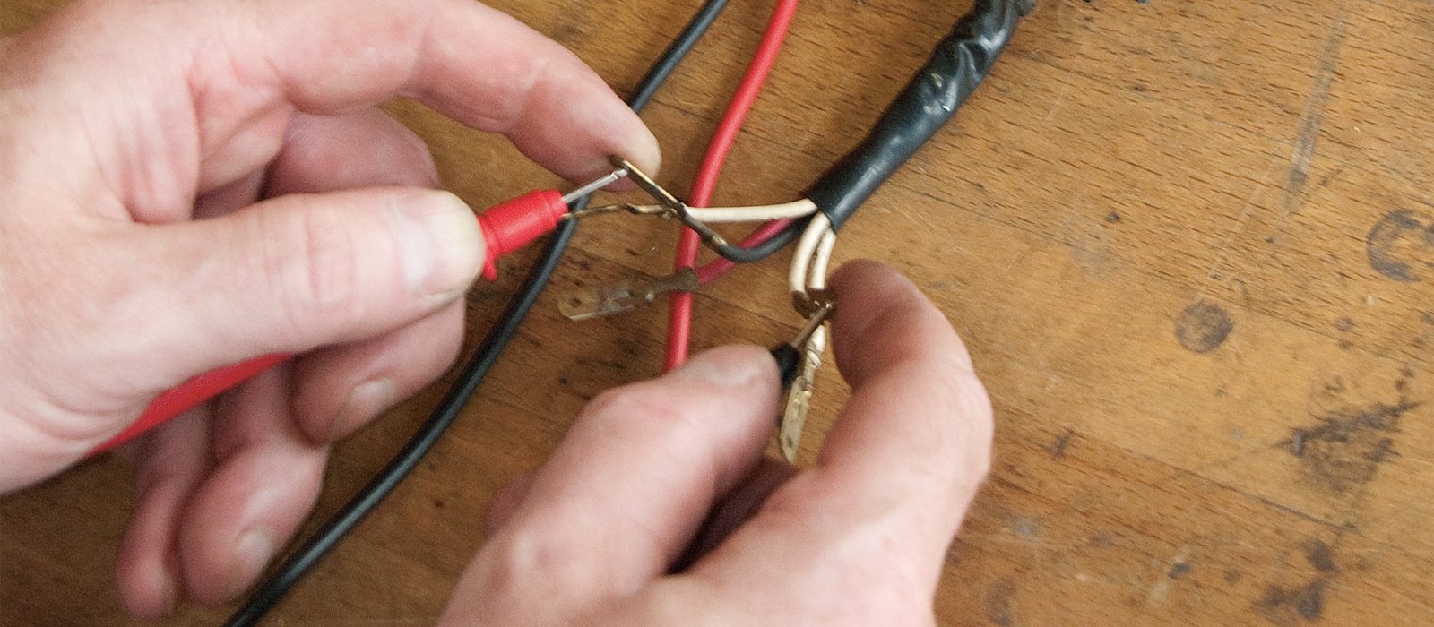
How to Test a Brushless Motor with a Multimeter: Resistance Check
To start, unplug the motor completely. You don't want stray voltage messing with your readings.
Set your multimeter to the lowest resistance range. Usually 200 ohms or less. If your meter has a relative mode. Use it to zero out the test lead resistance, this matters when you're chasing fractions of an ohm.
Then touch the probes to the three phase wires in pairs: U to V, V to W. U to W. Write down each value.
On a healthy motor. All three readings should match within about 10%. And the trend keeps going.
| Motor Type | Typical Phase-To-Phase Resistance |
|---|---|
| Small drone (2205) | 0.3 – 0.5 Ω |
| Medium drone (2212) | 0.5 – 0.8 Ω |
| Large drone (5010) | 1.0 – 2.5 Ω |
| Industrial BLDC | 2.0 – 10.0 Ω |
Nope, those numbers aren't typos. Brushless motors have very low DC resistance because they're designed to spin at thousands of RPM with minimal heat loss. 1 Ω—you've (and the data generally agrees) got a partially burnt winding. Zero ohms across any pair means a dead short inside the windings. 1 Ω.
In reality, that's still acceptable as long as all three measurements are consistent. 0. And stays there) almost consistently means the insulation between windings has melted. An infinite reading, of course, tells you the wire is broken. Yet, context matters heavily.
Here's a frustration. 5 ohm resistances. You might think the motor is shorted when it's not. If you're getting suspiciously low numbers, test a known good motor of the same type to see if your meter is even capable.
Once you've confirmed the resistances are equal, the windings are probably intact. This test alone catches most stator failures. Still, it won't tell you about damaged magnets or a bent shaft, which means for that, you need the next checks.
Short to Ground Test: Is the Casing Live?
Now switch your meter to continuity mode (the one that beeps). Touch one probe to any phase wire—any will do—and the other probe firmly to the metal motor casing. Silence, no beep.
That means the insulation layer on the copper wire has failed. And electricity can leak to the frame.
This is a dangerous condition, especially in high-voltage applications. A short to ground can fry your ESC, trigger a fire. Or give you a nasty shock if the motor is mounted to a conductive chassis.
The fix? The motor is toast. You can't repair a shorted winding without rewinding the whole stator, which costs more than a new motor.
So, in plain English: blocksep matters. This brings up an interesting angle. Before condemning it, though, clean off any carbon dust or metallic debris stuck between every (depending entirely on the context) phase wires and the case. I've seen false beeps caused by a tiny flake of conductive crud.
Wipe it down and test again. Also, wiggle the phase wires gently while testing. And intermittent shorts that only appear when the wire moves can drive you nuts later.
If you get an open circuit (infinite resistance) between every phase and the casing, (which works out well in practice) the basic insulation is sound. Good. Move on to the active test.
Back EMF Test: The Drill Trick That Reveals a Dead Motor
Here's where we get empirical. Try it out.
A brushless motor is — basically; a generator. Spin the shaft and it produces voltage. No voltage? Something is mechanically or magnetically broken.
But here's the catch: hand-spinning is wildly inconsistent. Your wrist can't sustain a steady RPM.
So the multimeter may show flickering numbers that are tricky to trust. Instead, chuck a drill onto the motor shaft. Use a small adapter if needed.
Set your multimeter to AC voltage, not DC. Yes, the motor generates AC back EMF; now, spin the motor with the drill at a moderate speed, maybe 800 to 1500 RPM.
Puts things in perspective. Measure the voltage between any two phase wires. 5V up to 2V for small drone motors. And higher for larger industrial BLDCs.
If you see close to zero or nothing at all — you likely have a shorted turn — broken magnet, or seized bearing.
This is exactly what that first point lead to, why does this work? Because brushless motors rely on permanent magnets and coils interacting. Even a slight defect in the magnetic circuit kills the generated voltage.
And this test is especially helpful if the resistance check passed but the motor still won't spin under load. It tells you the motor's core electromagnetic health.
If you don't own a drill, you can still try hand-spinning. But accept that results will be iffy. If your motor passes all tests but still doesn't perform. A classic case in point is when a RC car loses reverse, that's almost not once a motor fault.
As we explain in this guide on why your RC car won't go in reverse.
Hall Sensor Testing: Only for Sensored Motors
From a broader view, not all brushless motors have Hall sensors. Unless you're working with a sensored motor (often used in RC cars for smooth low-speed control), skip this section.
Hall sensors tell the ESC exactly. Where the rotor is, so the timing is perfect.
Yet, when one fails, the motor stutters, cogs, or just won't start.
To test them. You need a 5V DC power supply, a spare ESC's BEC output works, or a bench supply. Connect 5V to the sensor's red wire and ground to black.
Then measure the signal wire (regularly white. Or yellow) with your multimeter on DC voltage. Slowly rotate the shaft by hand.
The voltage should toggle cleanly between 0V. And 5V as each magnet passes.
Actually, if it sticks high or low, that sensor is dead.
Still, check all three Hall signal wires. Uneven or missing toggles mean at least one sensor is faulty. Some motors let you replace individual sensors. But — or rather, often it's easier to swap the whole motor.
When to Go Further: Insulation Testing and Final Thoughts
You've done the basics. Everything checks out. Which means's when you break out a megohmmeter (insulation tester).Normal readings (as one might expect) are between 600. Hard to ignore those numbers. If it drops below 20 megohms, moisture or winding damage is compromising the insulation, and failure is imminent.
Though practical limits do exist.
What's the bottom line? But honestly, for hobbyists, a megohmmeter is overkill, by the time you've borrowed one, you could've (which is a critical factor) just replaced the motor. The multimeter tests catch most failures. In the ESC or the power delivery, if all those pass.
And the motor still stutters, the fault almost certainly lies. We covered that in detail when explaining why your RC car won't go in reverse.
You've now got a solid, repeatable diagnostic plan. The key here is that grab your multimeter, run through the checks in order, and you'll pinpoint whether the motor is the culprit. In nine out of ten cases, a cheap meter and; or rather, ten minutes of probing will give you a clear answer. That saves you from chasing ghosts and (at least based on current observations) buying parts you don't need.
However, nuance is required here.
🔍 Research Sources
Verified high-authority references used for this article